Acorn Atom Reworked
- Posted by andy
- Posted on April 26, 2024
- Uncategorized
- 1 Comment.
Acorn Atom Replica, Acorn Atom Copy.
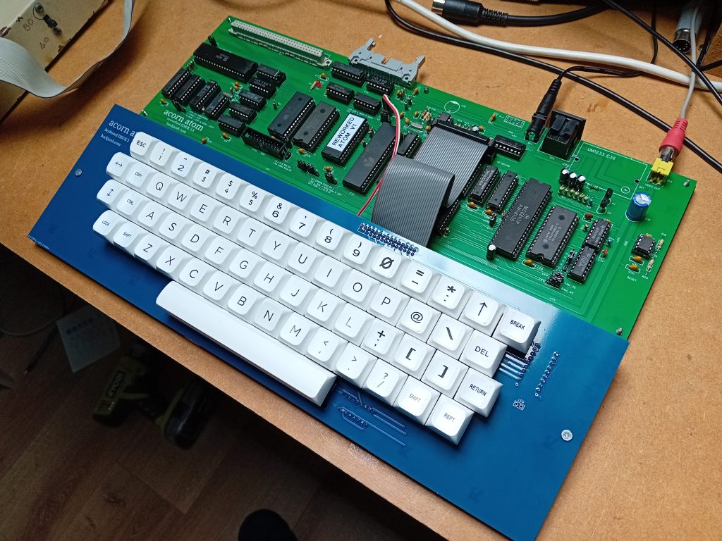
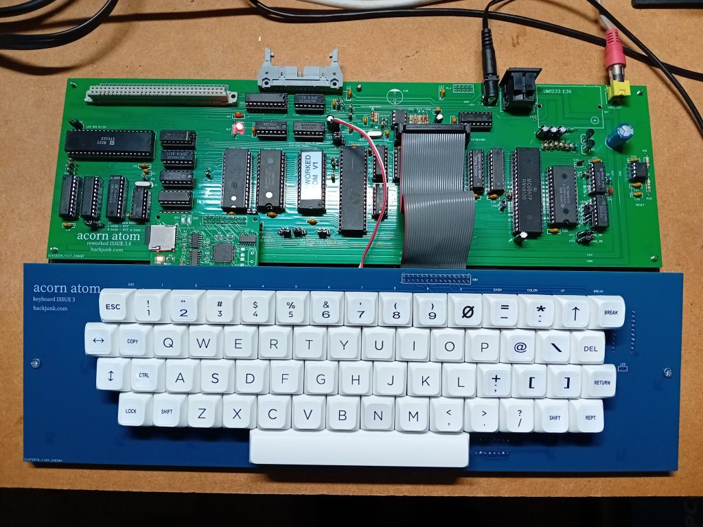
Hi everyone, I’ve been working on a replica Acorn Atom on and off over a year now and finally have a working prototype I’m happy with.
I’ve had a lot of issues with the video out. I just wanted a black and white output, the same as the original Atom, but have had problems with colour interference. After modifying the video clock circuit, adding extra smoothing I have a black and white output that seems to work on most displays.
I’ve made some improvements to the original design, while still using parts that were available in the 1980’s.
ACORN ATOM REWORKED PCB updates
- Reset circuit added
- 2114 RAM replaced with 64256 / 6264 chips
- 4K RAM switchable at #A000
- RAM from #0000 to #7FFF or #0000 to #03FF & #2000 to #7FFF
- 27512 ROM used giving two OS settings
- Noise killer circuit added
- 8304 chips replaced with 74LS245’s
- 81LS95 chips replaced with 74LS244’s
- Separate keyboard using Outemu switches (Cherry MX)
- Configurable CPU clock. 1, 2 or 4Mhz
- #B400 chip select added to expansion port
- Video out connector added
- CPU clock circuit improved
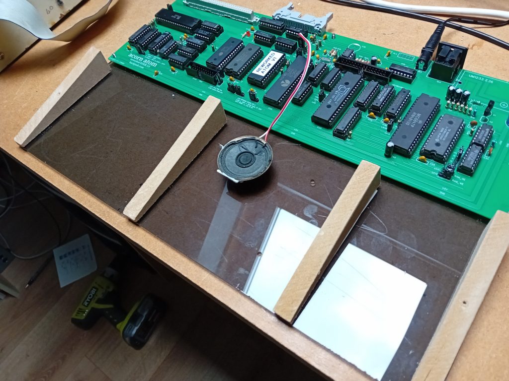
I am currently working on a 3D printed case. It will hopefully be in four parts and glued together.
I’ve used white keys on the keyboard as it’s easier to print labels for the non standard keys.
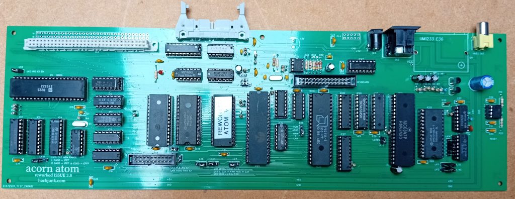
Some earlier versions.
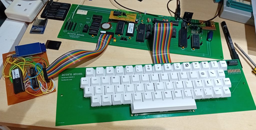
Early version with disk interface.
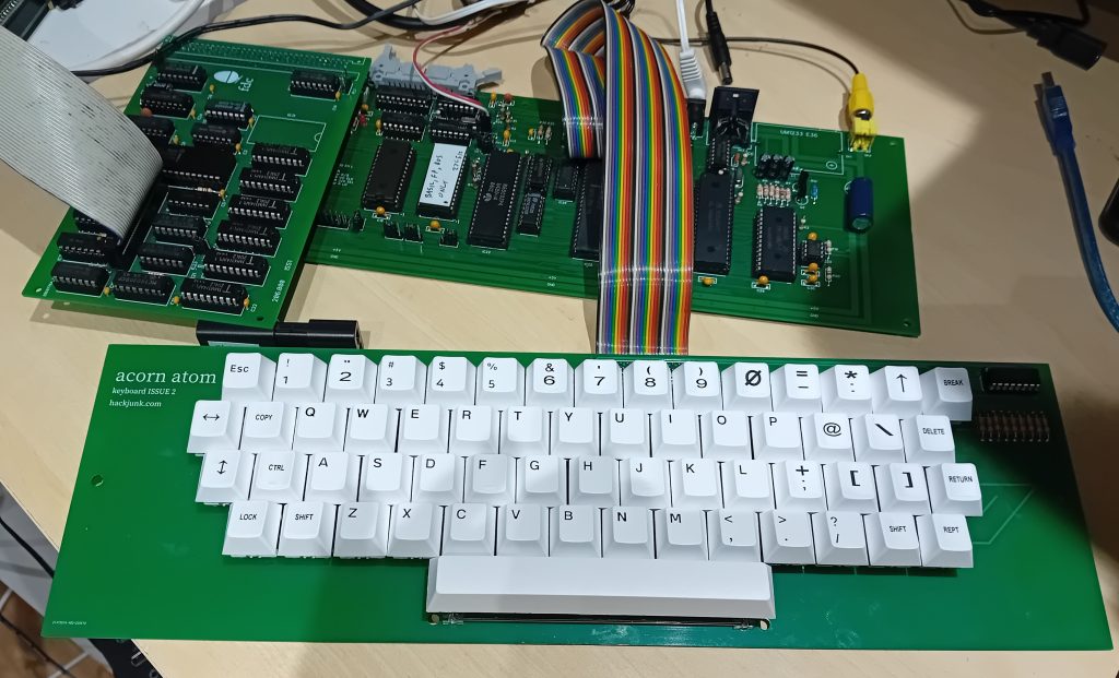
Acorn Atom Reworked Issue 3.8 Part List
Name | Designator | Footprint | Qty | Part No. | Supplier | Notes |
10nf | C1 | CAP_2.54_CERAMIC | 1 | |||
22uF | C2,C3,C4,C5,C8 | CAP-D3.0XF1.5 | 5 | |||
10nF | C6 | CAP_2.54_CERAMIC | 1 | |||
47nF | C7,C9 | CAP_2.54_CERAMIC | 2 | |||
33pF | C10,C11 | CAP_2.54_CERAMIC | 2 | |||
1000uF | C12,C38 | CAP-TH_BD10.0-P5.00-D0.6-FD | 2 | |||
100nF | C13,C14,C15,C16, C17,C18,C19,C20, C21,C22,C23,C24, C25,C26,C27,C28, C29,C30,C31,C32, C36,C37,C39 | CAP_5MM_CERAMIC | 23 | |||
100pF | C33,C34 | CAP_2.54_CERAMIC | 2 | |||
10uF | C40 | CAP-D3.0XF1.5 | 1 | |||
6522 | IC1 | DIP40 | 1 | |||
74LS244 | IC2,IC3,IC27,IC28, IC50 | DIP20 | 5 | |||
74LS245 | IC4,IC29 | DIP20 | 2 | |||
74LS27 | IC5 | DIP14 | 1 | |||
74LS04 | IC6,IC45 | DIP14 | 2 | |||
62256 | IC10,IC12,IC32 | DIP28 | 3 | |||
74LS00 | IC8,IC11,IC48 | DIP14 | 3 | |||
74HCT573 | IC13 | DIP20 | 1 | |||
74LS08 | IC14 | DIP14 | 1 | |||
74LS14 | IC15 | DIP14 | 1 | |||
W27C512 | IC20 | DIP28 | 1 | Winbond | ||
74LS30 | IC21 | DIP14 | 1 | |||
6502 | IC22 | DIP40 | 1 | |||
74LS138 | IC23 | DIP16 | 1 | |||
8255 | IC25 | DIP40 | 1 | |||
6847 | IC31 | DIP40 | 1 | |||
555 | IC33 | DIP8 | 1 | |||
74LS163A | IC47 | DIP16 | 1 | |||
74LS139 | IC49 | DIP16 | 1 | |||
CONN_2x15 | KB1 | CONN_2X15 | 1 | |||
1Mh | L1 | AXIAL-6.5X2.3(1/4W) | 1 | |||
3mm | LED1 | LED-3MM RED | 1 | |||
HDR-M-2.54_1x3 | LK1,LK4,LK6,LK7 ,LK8,LK10,LK11, LK12 | HDR-M-2.54_1X3 | 8 | |||
HDR-M-2.54_1x2 | LK2,LK3,LK5,LK9, LK13,SPK1 | HDR-M-2.54_1X2 | 6 | |||
HDR-M-2.54_1x5 | LK14 | HDR-M-2.54_1X5 | 1 | |||
HDR-M-2.54_2x5 | PL4 | HDR-M-2.54_2X5 | 1 | |||
HEADER_26_PIN | PL5 | CONN_2X13 | 1 | |||
ATOM_EXPANSION_ 64PIN | PL6/7 | HEADER_2X64_A | 1 | |||
HDR-M-2.54_2x10 | PL8 | HDR-M-2.54_2X10 | 1 | |||
BC547B | Q1,Q2 | BC547 | 2 | |||
4K7 | R1,R2,R13,R14, R15,R16,R21,R26, R28,R29,R39,R40, R41 | 1/4W 5% | 13 | |||
470R | R3,R4,R5,R12 | 1/4W 5% | 4 | |||
82R | R6 | 1/4W 5% | 1 | |||
8K2 | R7 | 1/4W 5% | 1 | |||
3K3 | R8 | 1/4W 5% | 1 | |||
1K | R9,R22,R30 | 1/4W 5% | 3 | |||
270R | R10,R24 | 1/4W 5% | 2 | |||
3K9 | R11 | 1/4W 5% | 1 | |||
2.2K | R17 | 1/4W 5% | 1 | |||
1M | R19,R20 | 1/4W 5% | 2 | |||
10K | R23 | 1/4W 5% | 1 | |||
1M | R27 | 1/4W 5% | 1 | |||
4k7 | R31,R32,R36 | 1/4W 5% | 3 | |||
47k | R33,R34 | 1/4W 5% | 2 | |||
470k | R35 | 1/4W 5% | 1 | |||
10k | R37 | 1/4W 5% | 1 | |||
UM1233 E36 | SK1 | UM1233 | 1 | |||
7_PIN_DIN_PCB | SK2 | 7_PIN_DIN_PCB | 1 | 2989968 | Farnell | |
DC005-2.5MM | SK3 | DC-IN-TH_DC-005-20A | 1 | 259-6425 | RS | |
rca connector | SK4 | RCA CONNECTOR | 1 | 189-3957 | RS | |
3.58MHz | X1 | OSC-49S-1 | 1 | |||
4Mhz | X2 | OSC-49S-1 | 1 | |||
74LS02 | IC7 | DIP14 | 1 | |||
74HC04 | IC26 | DIP14 | 1 | |||
74LS393 | IC44 | DIP14 | 1 | |||
LM348 | IC46 | DIP8 | 1 |
IC26 must be HC version for CPU clock to run
IC11 must be LS version for video clock to run
Ribbon cable & connectors
Keyboard
Name | Designator | Footprint | Qty | Part No. | Supplier | Notes |
MX 1.0U | C1 | CHERRY MX | 60 | Outemu | ||
KB1 | KB1 | HDR-M-2.54_2x15 | 1 | |||
LED | LED | HDR-M-2.54_1X2 | 1 | Optional | ||
4K7 | R17-R25 | 1/4W 5% | 9 | |||
2K2 | R40 | 1/4W 5% | 1 | Optional |
Outemu switches, keycaps and spacebar stabilizer from Aliexpress
Spacebar is 6.25U
I used the black switches as these give a nice, non clicky feel.
Some keycaps require a sticker for the correct keyboard designation
Some labels for the keyboard I made
Link Settings
LK1 EPROM #E000 enable left
LK2 Enable IRQ for IC1
LK3 PL8 IRQ Enable
LK4 CPU, left 1MHz, right 2MHz, up 4MHz
LK5 4MHz clock to IC44
LK6 Left RAM at #0000 – #03FF & #2000 – #7FFF, Right RAM at #0000 – #7FFF
LK7 System ROM left low (#0000 – #7FFF), right high (#8000 – #FFFF)
Mapped to;
#A000 – #AFFF (if selected, Extension ROM)
#C000 – #CFFF BASIC
#D000 – #DFFF Floating Point
#E000 – #EFFF Atommc2 or Floppy disk
#F000 – #FFFF Kernal
LK8 #A000 ROM, RAM select.
ROM selected will enable data at #A000 – #AFFF in system ROM
RAM selected will enable IC12 #A000 – #AFFF
LK9 #A000 RAM enable, required if LK8 is set to RAM
LK10 Expansion port data bus select
Left #0400 – #1FFF, right #0400 – #1FFF and #E000 – #EFFF
Noise Killer
LK11 RAM_OE
LK12 RAM_WE
LK13 LOAD
LK14 VDG delay
Default settings
LK1 Left
LK2 Fitted
LK3 Not Fitted
LK4 Left
LK5 Fitted
LK6 Right
LK7 Left
LK8 Down
LK9 Fitted
LK10 Left
LK11 Right
LK12 Right
LK13 Fitted
LK14 CE-1G
System ROM W27C512 Winbond 64K
Kernal ROM mapping
Lower setting Maps to;
#0000 – #1FFF #8000 – #9FFF NOT USED (Video RAM)
#2000 – #2FFF #A000 – #AFFF Willow 2 Extension ROM (LINK #A000)
#3000 – #3FFF #B000 – #BFFF NOT USED (I/O)
#4000 – #4FFF #C000 – #CFFF BASIC ROM
#5000 – #5FFF #D000 – #DFFF Floating point ROM
#6000 – #6fff #E000 – #EFFF ATOMMC2 V2.9
#7000 – #7FFF #F000 – #FFFF Kernal ROM
Upper setting Maps to;
#8000 – #8FFF #8000 – #9FFF NOT USED (Video RAM)
#A000 – #AFFF #A000 – #AFFF AEK Monitor Extension ROM (LINK #A7C7)
#B000 – #BFFF #B000 – #BFFF NOT USED (I/O)
#C000 – #CFFF #C000 – #CFFF BASIC ROM
#D000 – D5FFF #D000 – #DFFF Floating point ROM
#E000 – #Efff #E000 – #EFFF DOS
#F000 – #FFFF #F000 – #FFFF Kernal ROM
CREDITS
Noise Killer – Hoglet67
Atommc2 – Charlie Robson – (Sir Morris)
Hello,
I really like your build!
I got my eyes on Acorn when they released the Atom and have been in the process of getting one from time to time.
They are getting a quite old so it makes more sense to build a clone and to put a 3D printed shell on it.
Is there any possibility to buy a circuit board from you or the CAD drawing?
Thanks in advance
//Fred