
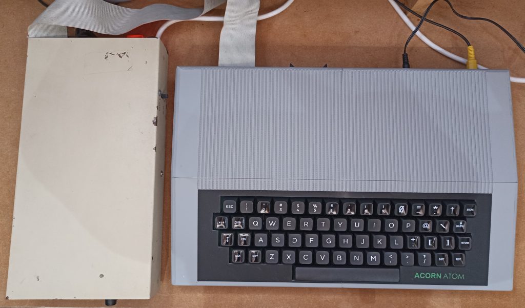
Acorn Atom reworked
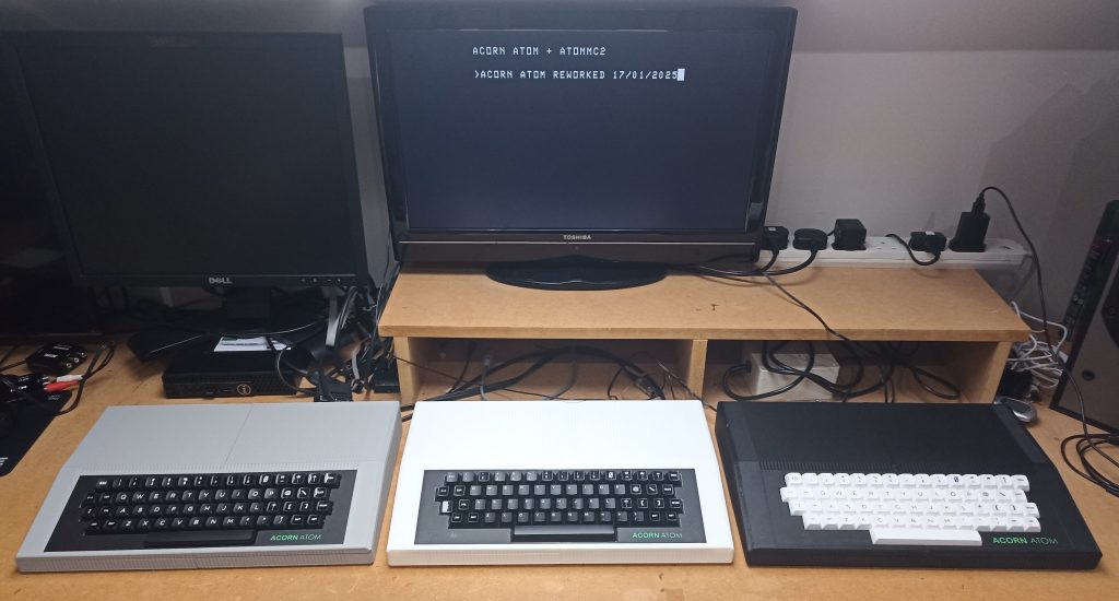
This is my version of the Acorn Atom computer, with a few improvements.
I’ve tried to make it easy to build by only using through hole components which were mostly available in the 1970’s.
This version has 40K RAM, 4K RAM at #A000, Screen noise killer circuit etc.
I’ve also designed a case which can be 3D printed.
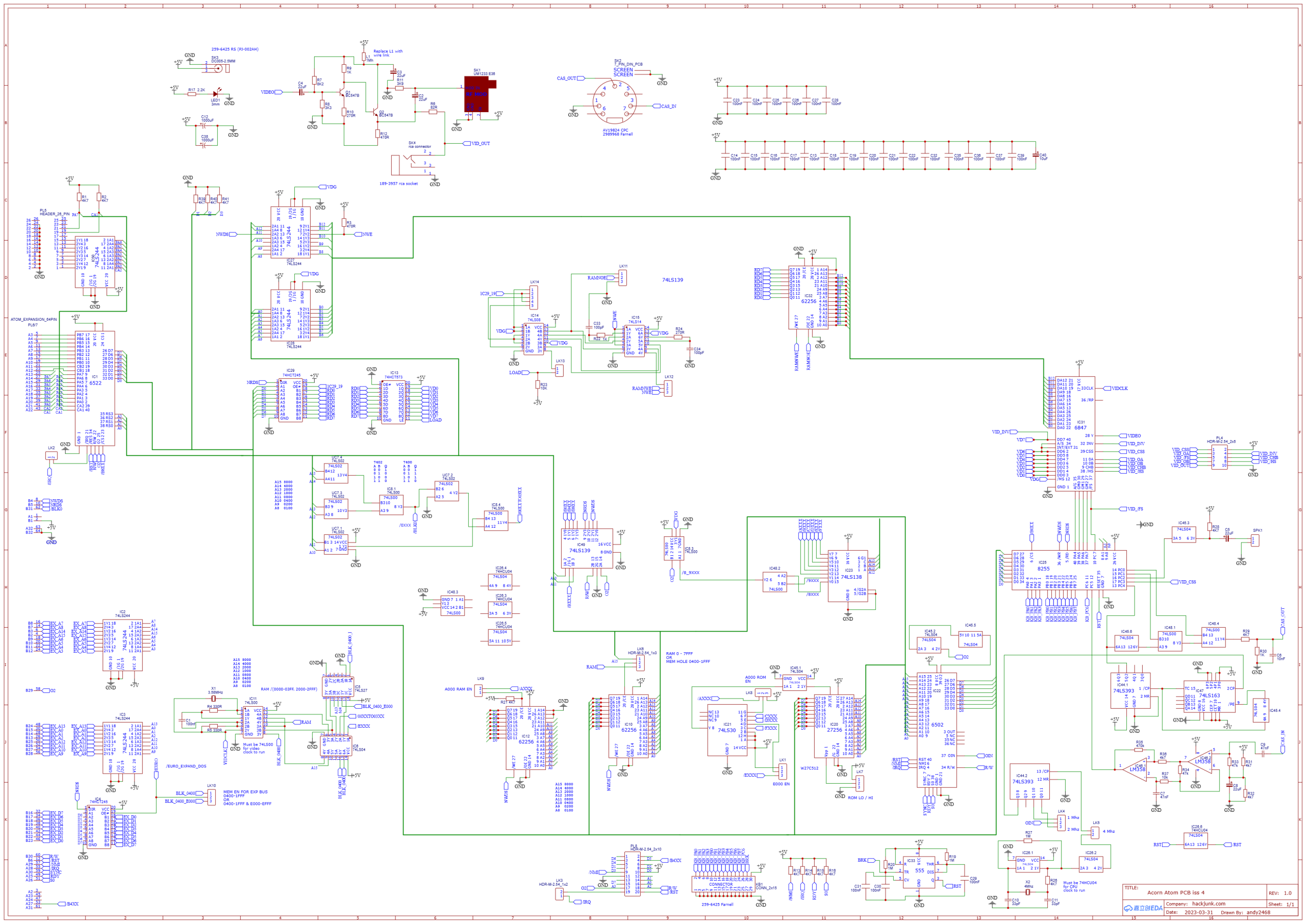
ACORN ATOM REWORKED PCB updates
- Reset circuit added
- 2114 RAM replaced with 62256 / 6264 chips
- 44K RAM (#0000 to #9FFF, #A000 to #AFFF switchable)
- 64K ROM used giving two OS settings (ATOMMC2 or floppy disk)
- Noise killer circuit added for flicker free graphics
- Obsolete buffer chips replaced with 74 series
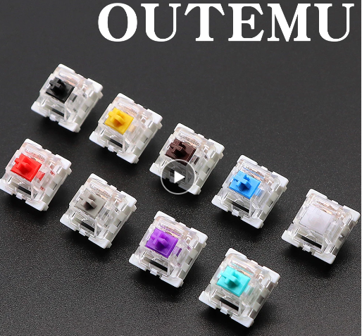
- Separate keyboard using Outemu switches (Cherry MX)
- CPU clock configurable – 1, 2 or 4Mhz
- #B400 chip select added to expansion port
- Video out connector added
- No surface mount components
- All parts readily available
Building the Atom Reworked

Interactive BOM
Parts List
| PREFIX | Component | Quantity |
| C6 | 10nf | 1 |
| C2,C3,C4,C5,C8 | 22uF | 5 |
| C7,C9 | 47nF | 2 |
| C10,C11 | 33pF | 2 |
| C12,C38 | 1000uF | 2 |
| C1,C13,C14,C15,C16,C17,C18, C19,C20,C21,C22,C23,C24, C25,C26,C27,C28,C29,C30, C31,C32,C35,C36,C37,C39 | 100nF C1 2.54mm pitch Rest 5mm pitch | 25 |
| C33,C34 | 100pF | 2 |
| C40 | 10uF | 1 |
| R1,R2,R13,R14,R15,R16, R21,R26,R28,R29,R31, R32,R36,R39,R40,R41 | 4K7 | 16 |
| R3,R12 | 470R | 2 |
| R4,R5 | 330R | 2 |
| R6 | 82R | 1 |
| R7 | 8K2 | 1 |
| R8 | 3K3 | 1 |
| R9,R22,R30 | 1K | 3 |
| R10,R24 | 270R | 2 |
| R11 | 3K9 | 1 |
| R17 | 2.2K | 1 |
| R19,R20 | 1M | 2 |
| R23 | 10K | 1 |
| R27 | 1M | 1 |
| R33,R34 | 47k | 2 |
| R35 | 470k | 1 |
| R37 | 10k | 1 |
| Q1,Q2 | BC547B | 2 |
| X1 | 3.579545MHz H49S | 1 |
| X2 | 4Mhz H49S | 1 |
| L1 | Wire link | 1 |
| LED1 | 3mm RED | 1 |
| IC7 | 74LS02 | 2 |
| IC26 | MUST BE 74HCU04 | 1 |
| IC44 | 74LS393 | 1 |
| IC46 | LM358 | 1 |
| IC1 | 6522 | 1 |
| IC2,IC3,IC27,IC28,IC50 | 74LS244 | 5 |
| IC4,IC29 | 74LS245 | 2 |
| IC5 | 74LS27 | 1 |
| IC6,IC45 | 74LS04 | 3 |
| IC10,IC12,IC32 | 62256 | 3 |
| IC8,IC48 | 74LS00 | 2 |
| IC11 | MUST BE 74LS00 | 1 |
| IC13 | 74HCT573 | 1 |
| IC14 | 74LS08 | 1 |
| IC15 | MUST BE 74LS14 | 1 |
| IC20 | W27C512 Winbond | 1 |
| IC21 | 74LS30 | 1 |
| IC22 | 6502 | 1 |
| IC23 | 74LS138 | 1 |
| IC25 | P8255A | 1 |
| IC31 | MC6847P | 1 |
| IC33 | 555 | 1 |
| IC47 | 74LS163 | 1 |
| IC49 | 74LS139 | 1 |
| LK1,LK4,LK6,LK7,LK8,LK10, LK11,LK12 | HDR-M-2.54_1x3 | 8 |
| LK2,LK3,LK5,LK9,LK13,SPK1 | HDR-M-2.54_1x2 | 6 |
| LK14 | HDR-M-2.54_1x5 | 1 |
| PL4 | HDR-M-2.54_2x5 | 1 |
| PL8 | HDR-M-2.54_2x10 | 1 |
| PL6/7 | ATOM_EXPANSION_64PIN | 1 |
| KB1 | CONN_2x15 | 1 |
| SK1 | UM1233 E36 | 1 |
| SK2 | 7_PIN_DIN_PCB | 1 |
| SK3 | DC005-2.5MM | 1 |
| SK4 | RCA connector | 1 |
NOTES
IC26 must be HCU version for CPU clock to run
IC11 must be LS version for Video clock to run
IC15 works best with a 74LS14 or 7414 (74HC14 gives noise)
All other 74’s should be OK with LS, HC etc
6502 – Cheap replica’s fail BCD tests and can have timing issues! Genuine old stock work best
Speaker 16 ohm 0.5W 40mm
EXPANSION CONNECTOR
Farnell 1096906 (Harting 09 02 264 6824) for internal use, female ![]()
Farnell 1106779 (Harting 09 72 164 6903) for internal use, male ![]()
Male right angle (no part code yet!) 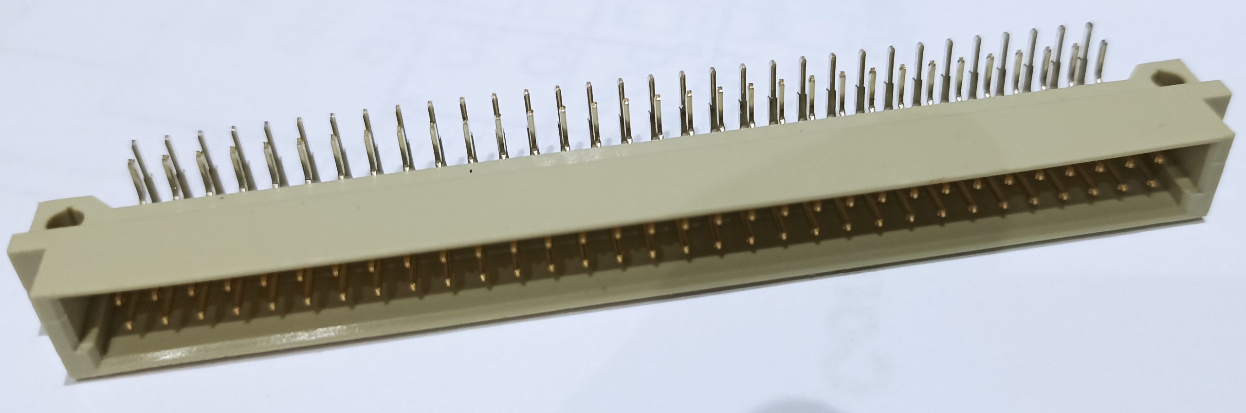
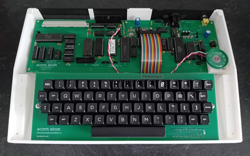
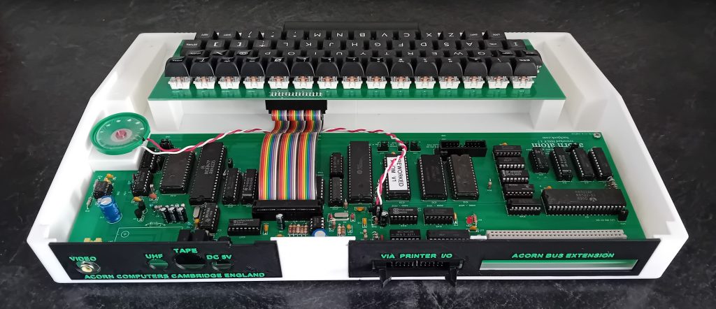
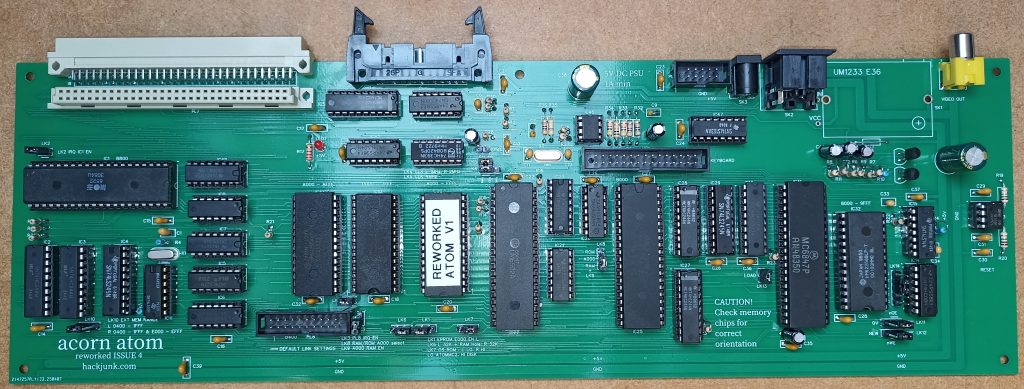
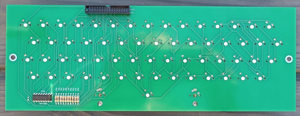
Main PCB
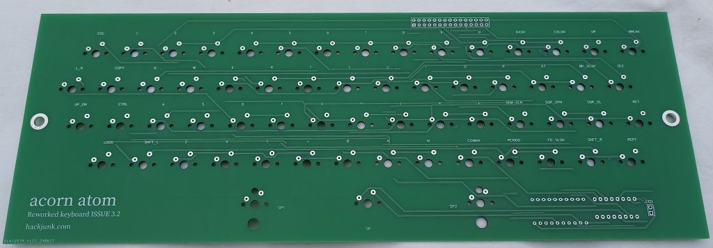
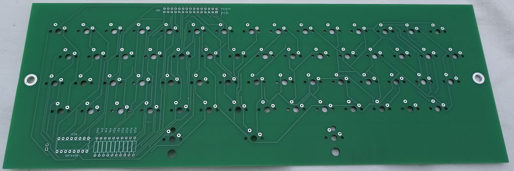
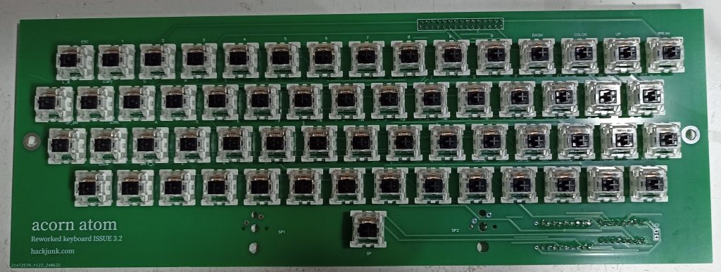
Keyboard
Top
Bottom
Keyboard Assembled
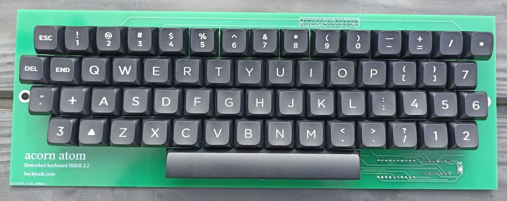
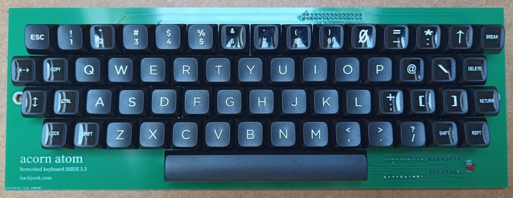
Assembled with Stickers
| Name | Designator | Footprint | Qty | Part No. | Supplier | Notes |
| MX 1.0U | Switch | CHERRY MX | 60 | Outemu | ||
| KB1 | KB1 | HDR-M-2.54_2x15 | 1 | |||
| LED | LED | 3mm | 1 | |||
| 4K7 | R17-25,40 | 1/4W 5% | 10 | |||
| IC26 | 7445 | dip 14 | 1 |
Outemu switches, keycaps and spacebar stabilizer from Aliexpress
Spacebar is 6.25U
I used the black switches as these give a nice, non clicky feel.
Some keycaps require a sticker for the correct keyboard designation
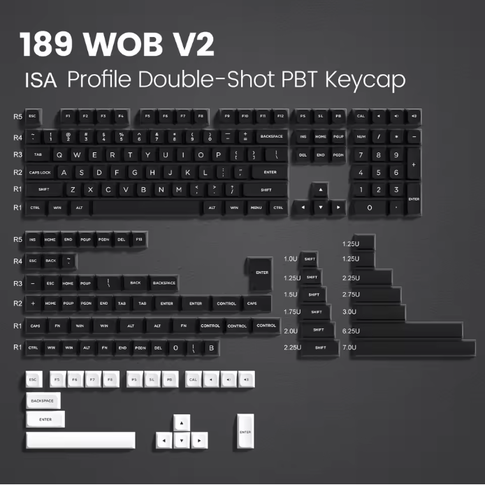
189 Key PBT Keycap Double-shot Green White ISA Keycaps Kit Backlit Key Cap Cherry MX For Wireless Mechanical Gaming Keyboards
Space bar stabiliser parts. Only the long bar is required, you have to buy the whole kit.
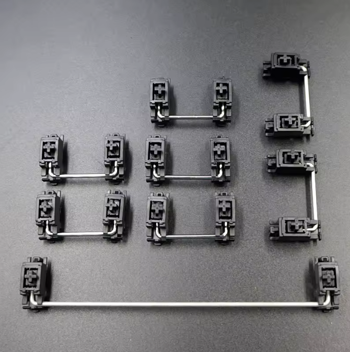
Customization PCB Satellite Axis For Cherry Mechanical Keyboard OEM Plate mounted Black 6.25u 2u Stabilizers Modifier Keys
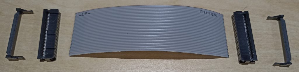
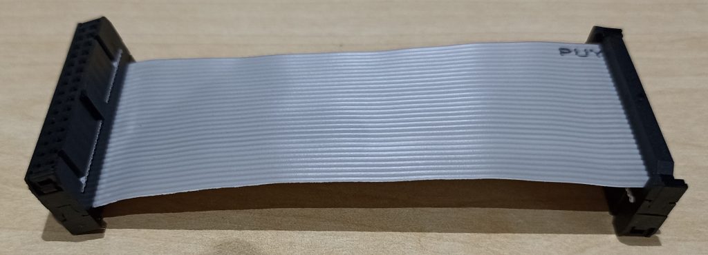
Keyboard Linking Ribbon
Cut ribbon to 125mm
Link Settings
LK1 EPROM #E000 enable left
LK2 Enable IRQ for IC1
LK3 PL8 IRQ Enable
LK4 CPU, left 1MHz, right 2MHz, up 4MHz
LK5 4MHz clock to IC44
LK6 Left RAM at #0000 – #03FF & #2000 – #7FFF, Right RAM at #0000 – #7FFF
LK7 System ROM left low (#0000 – #7FFF), right high (#8000 – #FFFF)
Mapped to;
#A000 – #AFFF (if selected, Extension ROM)
#C000 – #CFFF BASIC
#D000 – #DFFF Floating Point
#E000 – #EFFF Atommc2 or Floppy disk
#F000 – #FFFF Kernal
LK8 #A000 RAM/ROM select
ROM selected will enable data at #A000 – #AFFF in system ROM
RAM selected will enable IC12 #A000 – #AFFF
LK9 #A000 RAM enable, required if LK8 is set to RAM
LK10 Expansion port data bus select
Left #0400 – #1FFF, right #0400 – #1FFF and #E000 – #EFFF
Noise Killer
LK11 RAM_OE
LK12 RAM_WE
LK13 LOAD
LK14 VDG delay
Default settings
LK1 Left (Enable #E000 EPROM)
LK2 Fitted (6522 IRQ)
LK3 Not Fitted (PL8 interrupt)
LK4 Left (CPU 1Mhz)
LK5 Fitted (4Mhz clock)
LK6 Right (enable RAM from 0 – #7FFF)
LK7 Right (DOS ROM )
LK8 Down (RAM enable #A000)
LK9 Fitted (RAM select #A000)
LK10 Left (Memory hole @ #0400-#1FFF)
LK11 Right (Noise killer)
LK12 Right (Noise killer)
LK13 Fitted (Noise killer)
LK14 CE-1G (Noise killer)
System ROM W27C512 Winbond 64K
Kernal ROM mapping
Lower setting Maps to;
#0000 – #1FFF #8000 – #9FFF NOT USED (Video RAM)
#2000 – #2FFF #A000 – #AFFF Willow 2 Extension ROM (LINK #A000 to execute)
#3000 – #3FFF #B000 – #BFFF NOT USED (I/O)
#4000 – #4FFF #C000 – #CFFF BASIC ROM
#5000 – #5FFF #D000 – #DFFF Floating point ROM
#6000 – #6fff #E000 – #EFFF ATOMMC2 V2.9
#7000 – #7FFF #F000 – #FFFF Kernal ROM
Upper setting Maps to;
#8000 – #8FFF #8000 – #9FFF NOT USED (Video RAM)
#A000 – #AFFF #A000 – #AFFF AEK Monitor Extension ROM (LINK #A7C7 to execute)
#B000 – #BFFF #B000 – #BFFF NOT USED (I/O)
#C000 – #CFFF #C000 – #CFFF BASIC ROM
#D000 – D5FFF #D000 – #DFFF Floating point ROM
#E000 – #Efff #E000 – #EFFF DOS
#F000 – #FFFF #F000 – #FFFF Kernal ROM
CREDITS
Screen Noise Killer – Alan Knowles / Hoglet67
Atommc2 – Charlie Robson – (Sir Morris)
Case
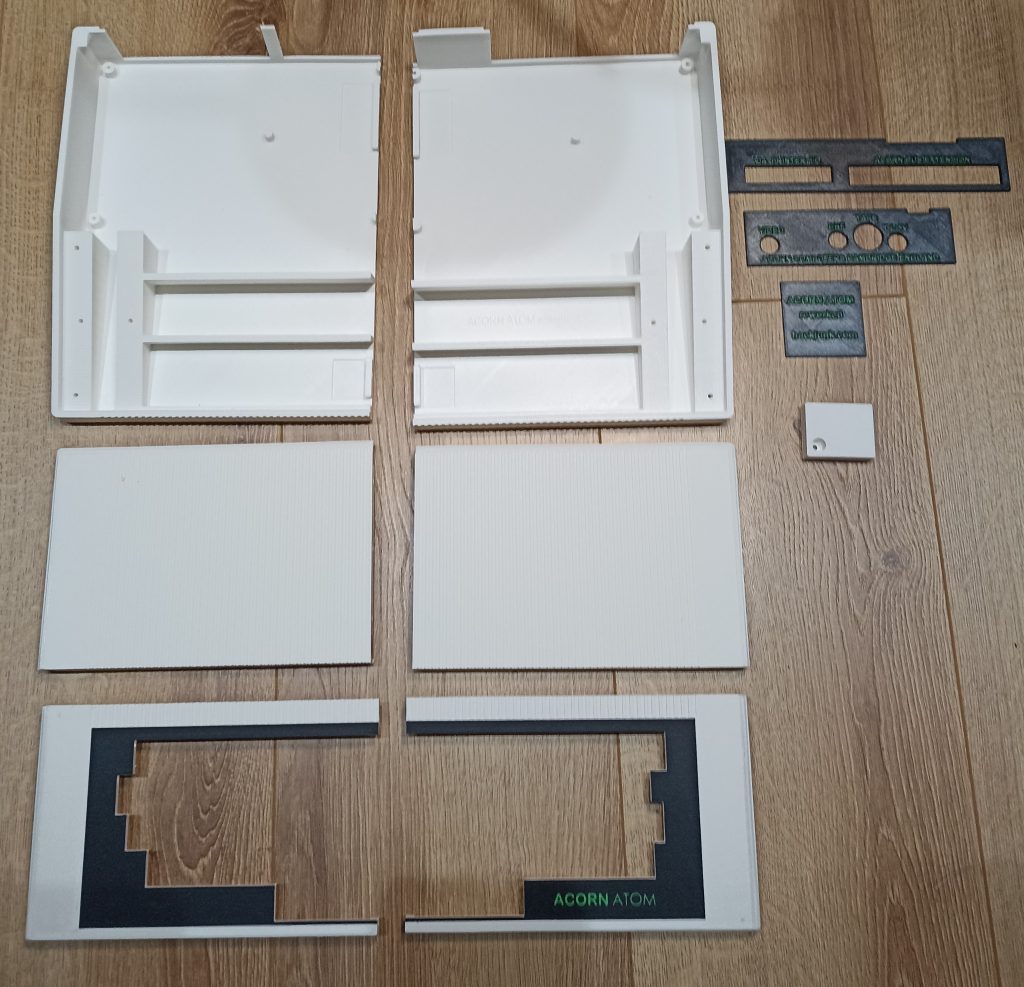
Printed using Bambu Lab X1 Carbon
Useful Info
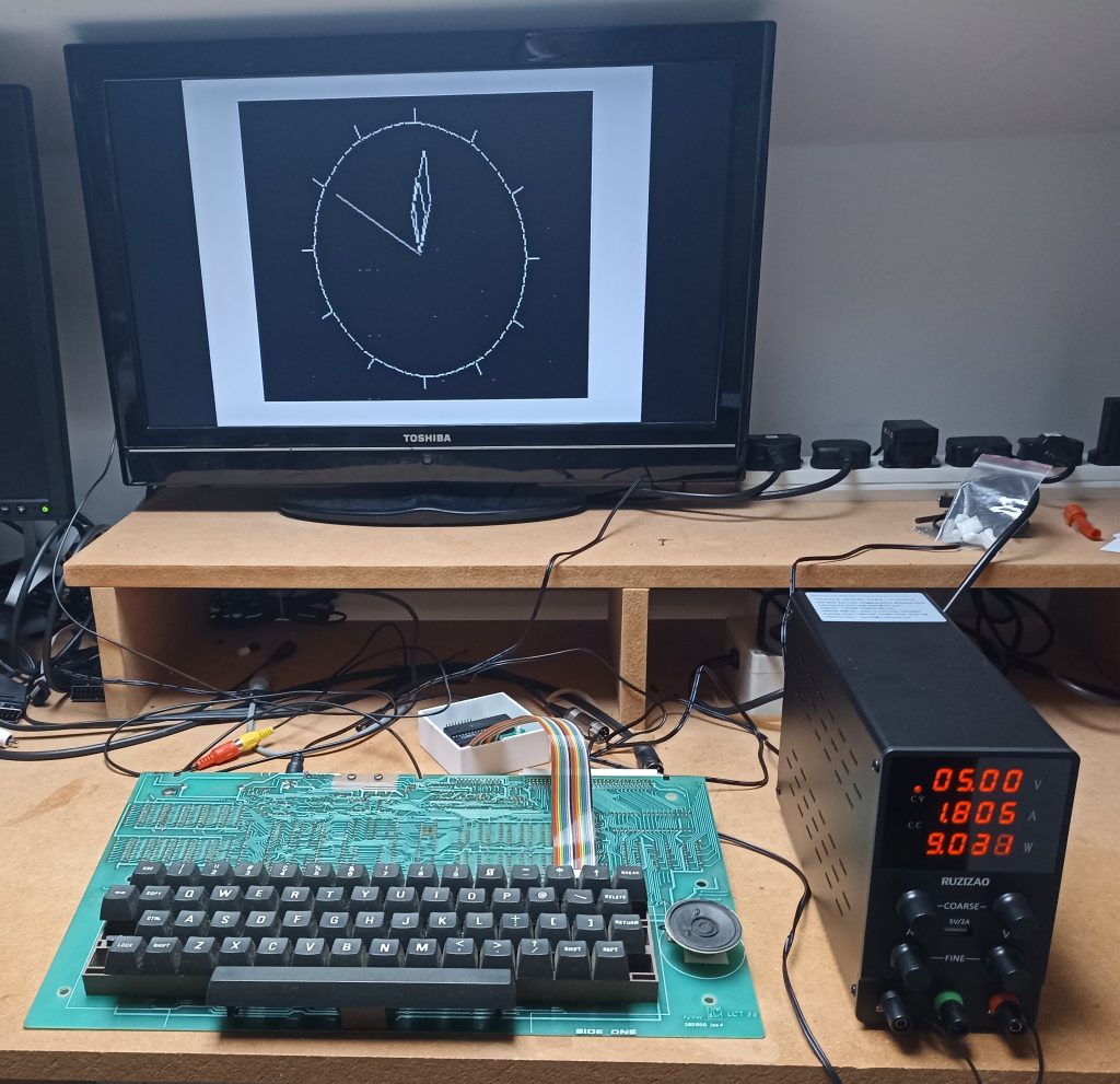
Original Atom draws 1.8 Amps with all chips fitted.
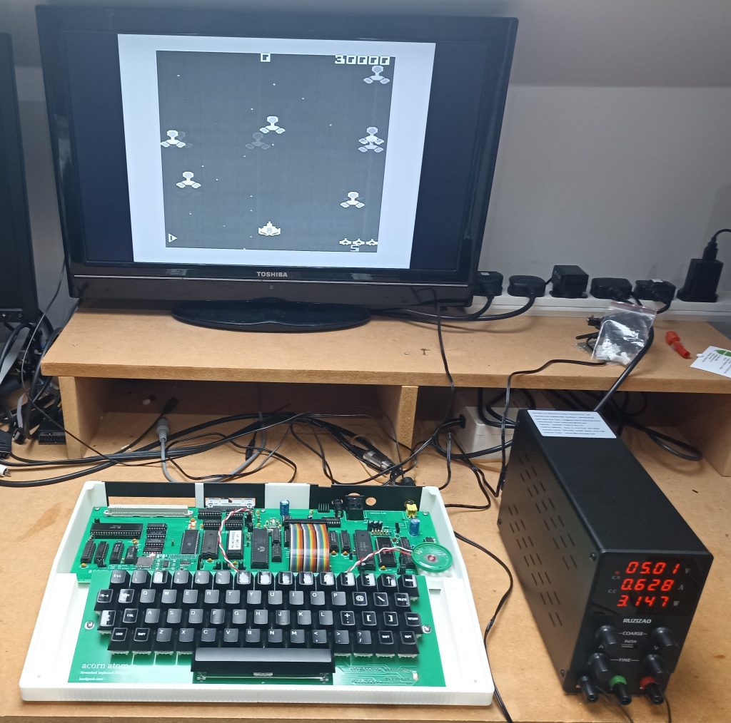
My version draws 0.6 Amps with all chips fitted.
I normally use a 5V 1 Amp power supply, which I’ve had running for hours with no issues.
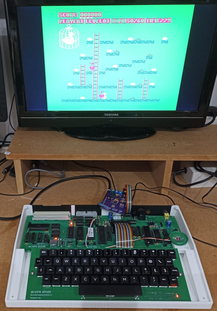
Colour test with RPI based RGB to HDMI board
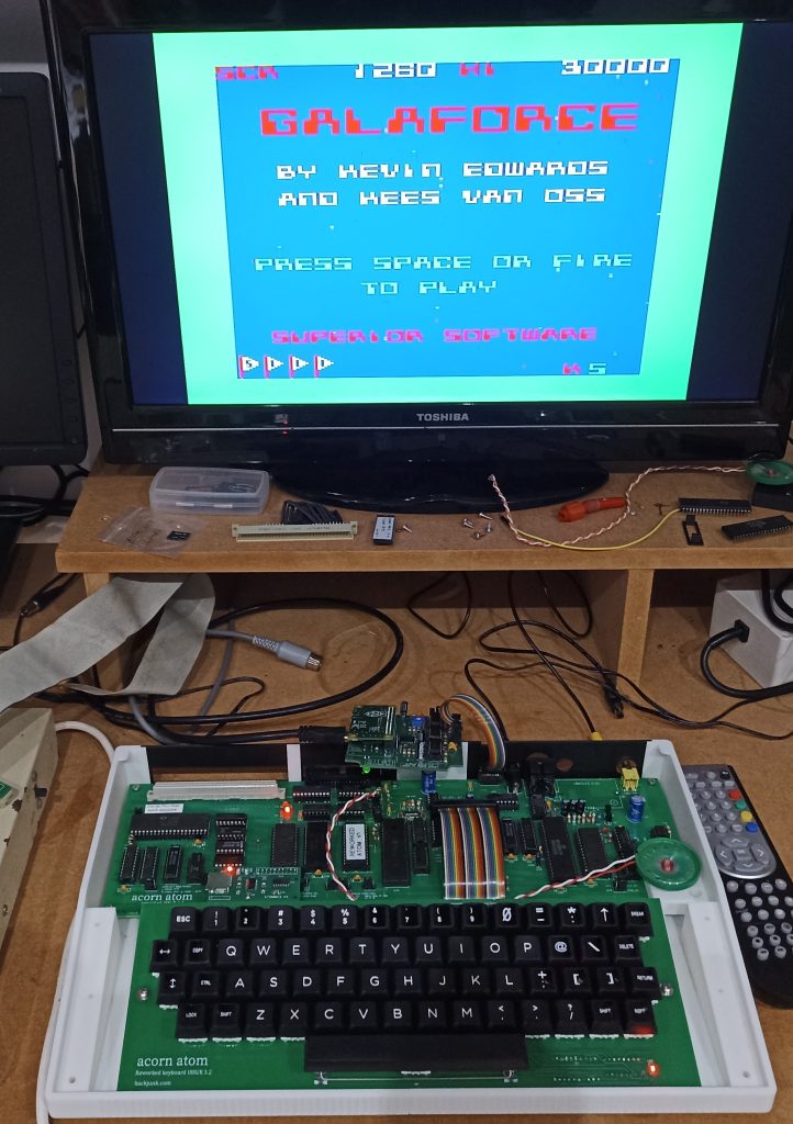
Colour test with Acorn Replica’s PCB
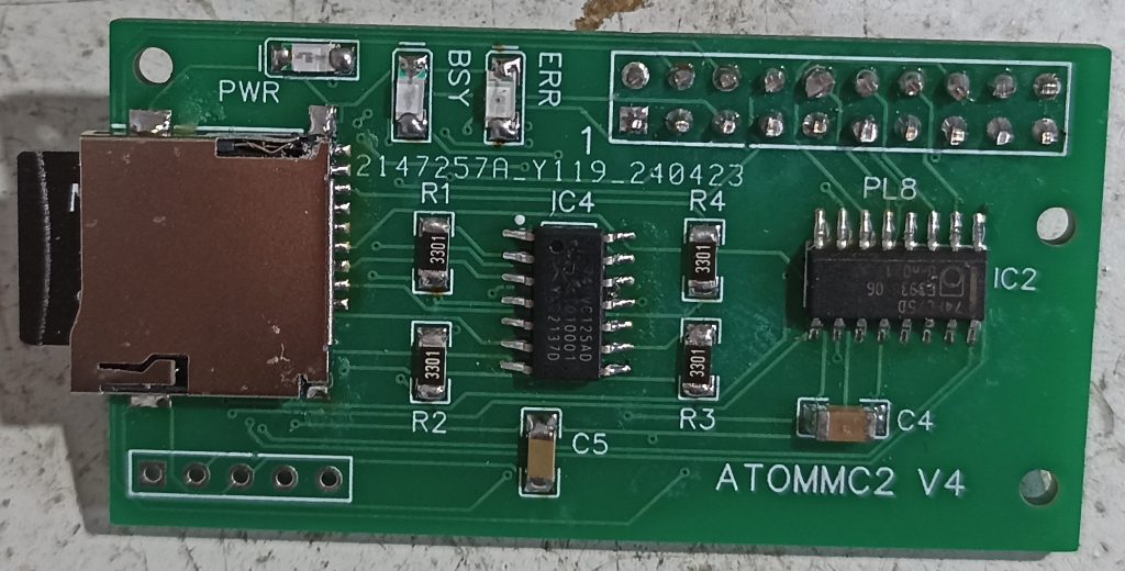
I also have a working internal fit floppy disk interface
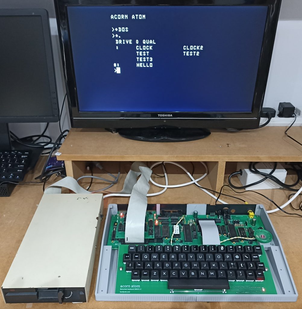
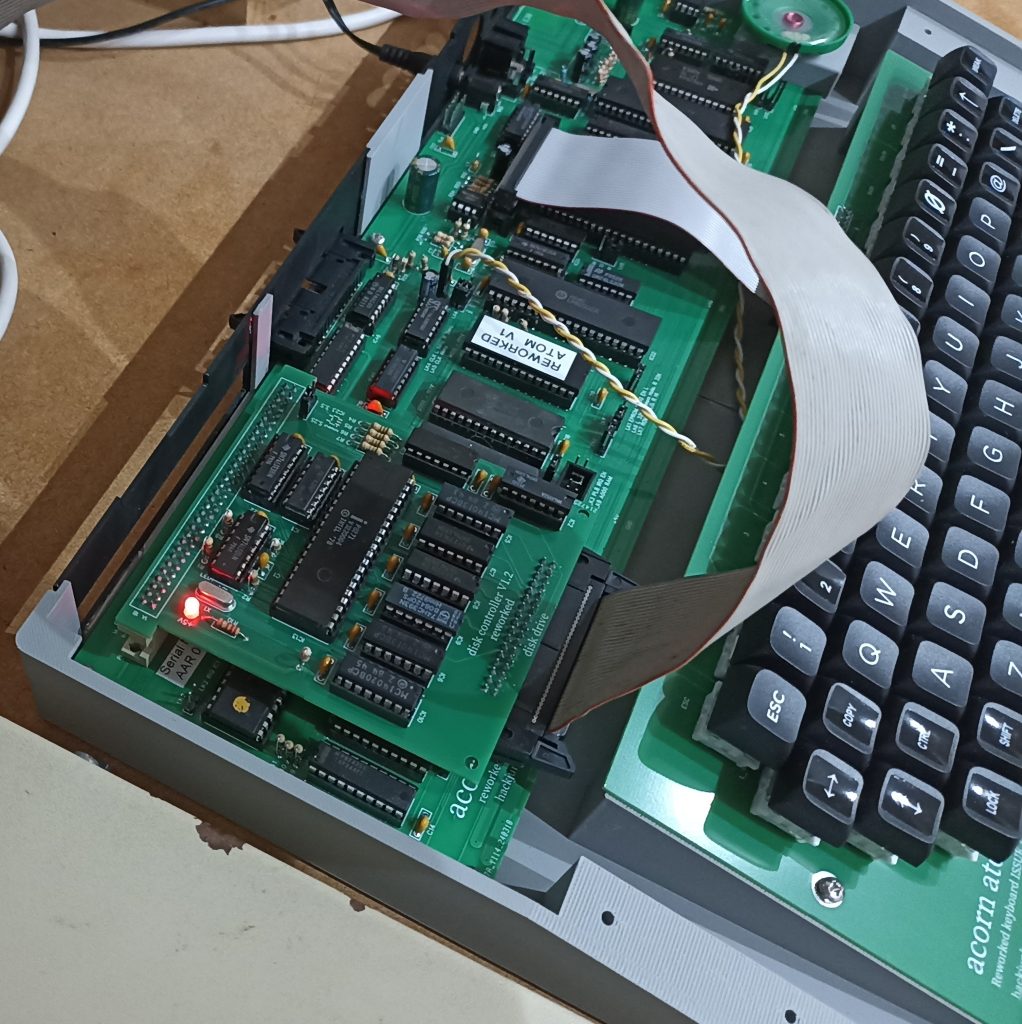
ATOMMC2 drive
I made my own version that sits neatly on the main PCB.
Contact info below

Hello
What a great project!
Does your version of the ATOMMC2 work on an original Atom? Do you sell them?
Thanks!
Hi
Yes it does work on the original Atom, however I don’t currently have any suitable EPROMS. If I can sort that out, I will sell them on ebay.
Hi, is your case design available at all?
I’m building one of your boards and would love to finish it off.
I’ve now added the 3d printer files to my website. They are located at the bottom of the pictures of the case parts.
Love how this re-imagined version of the Acorn Atom shows that with clever tweaks even 1970s hardware can feel fresh and buildable today.
Bentec Components & Trading Pte Ltd