
Vic 20 Replace BASIC and Kernal ROM’s with 27128 EPROM
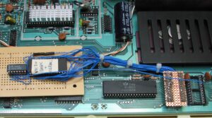
Vic 20 Replace BASIC and Kernal ROM’s with 27128 EPROM

I had a Vic 20 with a faulty BASIC ROM and thought it would be nice to combine the BASIC
and Kernal ROM’s into one. This gives you the ability to modify the standard ROM's.

The conversion is pretty simple. The only issues are the two chip select lines that need
 to be combined into one, and the Address 13 line to select the upper and lower 8k blocks
 of the EPROM. An AND gate will combine the chip selects and connecting A13 to the BASIC
 ROM chip select will ensure that the correct ROM is available when required.

Vic 20 Memory Map

 HEX  DEC                  USAGE                 8k    1k
 0000-03FF   0000-1023     System variables      BLK 0 RAM 0
 0400-0FFF   1024-4095     3K expansion RAM area B0    RAM 1,2,3
 1000-1DFF   4096-7679     User Basic area       B0    RAM 4-7
 1E00-1FFF   7680-8191     Screen memory         BLK 0 RAM 7
 2000-3FFF   8192-16383    8K expansion RAM/ROM  BLK 1
 4000-5FFF   16384-24575   8K expansion RAM/ROM  BLK 2
 6000-7FFF   24576-32767   8K expansion RAM/ROM  BLK 3
 8000-8FFF   32768-36863   4K Character ROM      BLK 4
 9000-93FF   36864-37887   I/O block 0           BLK 4
 9400-95FF   37888-38399   COL RAM,BLK 1 filled  BLK 4
 9600-97FF   38400-38911   Normal COLOR RAM      BLK 4
 9800-9BFF   38912-39935   I/O block 2           BLK 4
 9C00-9FFF   39936-40959   I/O block 3           BLK 4
 A000-BFFF   40960-49152   8K Expansion ROM      BLK 5
 C000-DFFF   49152-57343   8K BASIC ROM          BLK 6
 E000-FFFF   57344-65535   8K Kernal ROM         BLK 7
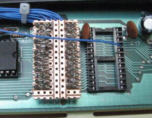
UD5 or UD11
 (901486-01)
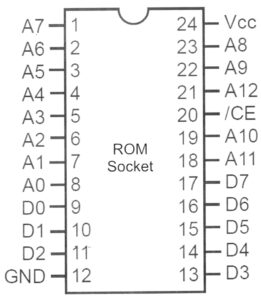
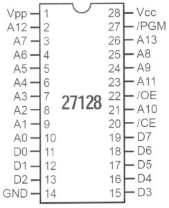
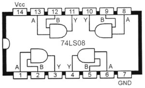
Acronyms
 /OE Output Enable (set low to enable data output from chip)
 /CE Chip Enable (set low to enable data output from chip)
 /CS Chip Select (same as Chip Enable)
 /PGM Program Mode (set low to program EPROM)
 Vpp Voltage used to program EPROM (usually 12.5 or 21V)

BASIC ROM socket to 27128
 A0-A12
 D0-D7
 Vcc to Vcc
 GND to GND

27128
 Pin 1 (Vpp) to Vcc
 Pin 20 (/CE) to GND
 Pin 27 (/PGM) to Vcc

74LS08
 Pin 7 to GND
 PIN 14 to Vcc
 Pin 1 to pin 26 (A13) of 27128
 Pin 1 to pin 20 (/CE) of BASIC ROM socket (BLK 6) UD5 or UD11
 Pin 2 to pin 20 (/CE) of Kernal Rom Socket (BLK 7) UD6 or UE12
 Pin 3 to pin 22 (/OE) of 27128

The chip select lines could also be taken from the 74LS138 (UB1 or UC5) or various
other points on the Vic motherboard.
Very cool mod! Did you just append the color ROM after the kernel ROM?